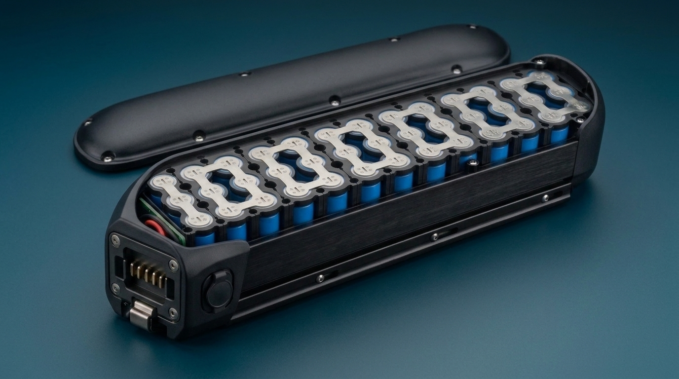
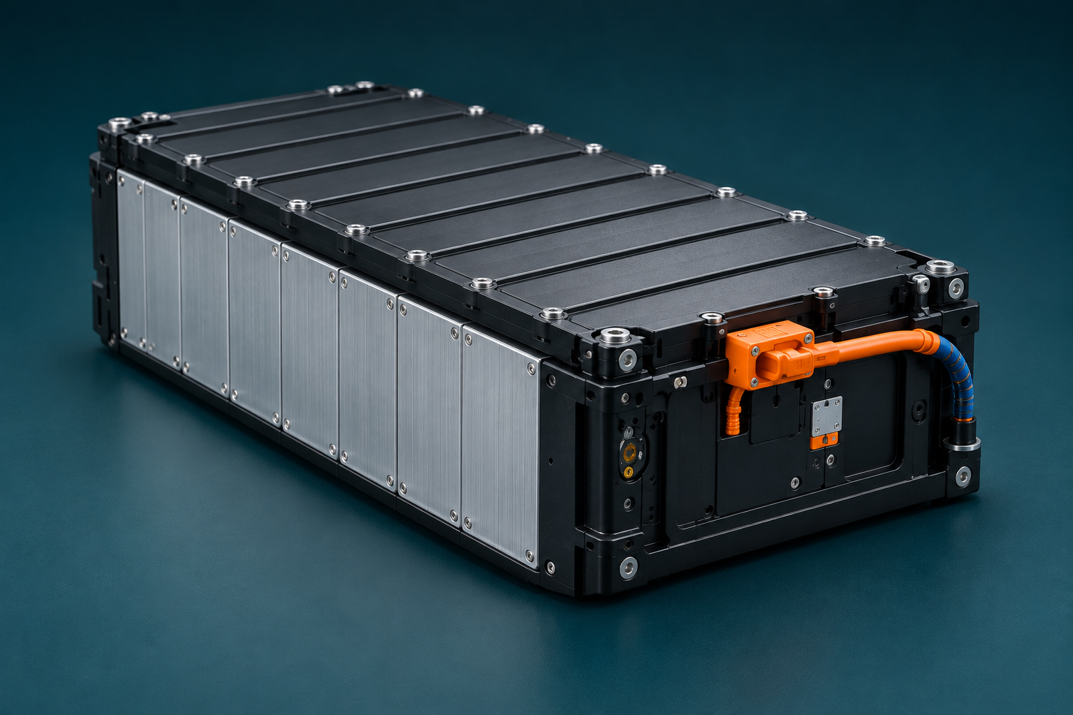
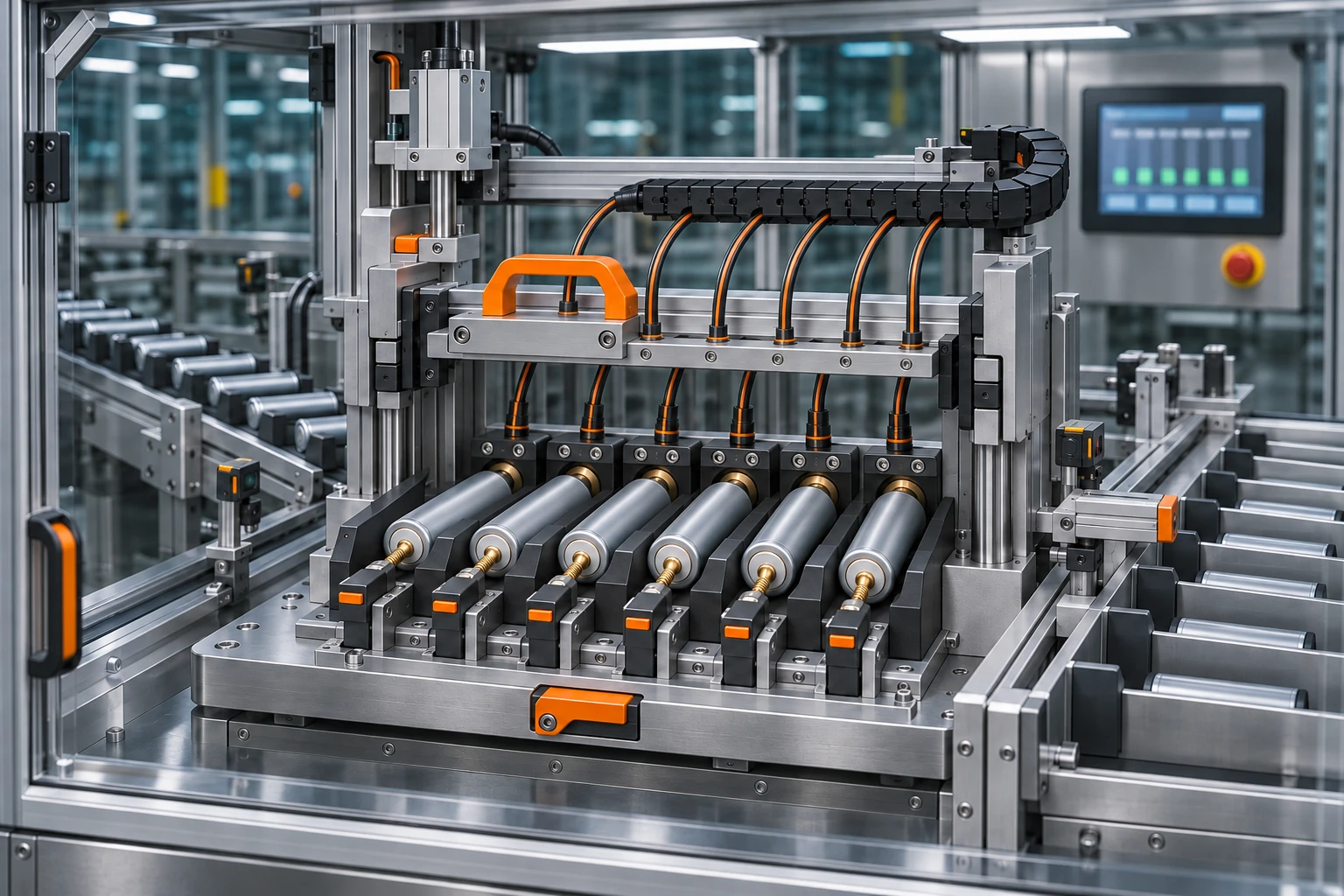
Small custom packs, E-bike batteries and large industrial systems. EBS adapts pack engineering and contract manufacturing to your product, connecting assembly, testing and traceability across formats.
CONCEPT IMAGE
01
01 / SMALL · COMPACT PACKS
Compact products.
A considered fit.
Flexible OEM manufacturing for small battery packs. Align cell layout, connections and enclosure requirements with the space inside your product.
One workspace, from compact products to industrial systems. Choose a cell and capacity, adjust the electrical configuration, explore how the pack fits your application, then add operating, interface and delivery requirements.
Holder dimensions242.3 × 75 × 72.7 mmCell support structure only; excludes BMS, wiring and connectors
Open “Dimensions & available space” to check fit
Explore the full cell library27 parameter profiles
Filter by format, capacity and chemistry, then apply a parameter profile to your 3D design. Codes distinguish specifications without selecting a brand.
27 / 27 parameter profiles
Parameter profile
Cell capacity
Nominal voltage
Reference envelope
Stated discharge limit
Use in design
18650 · C01Other · Catalog profile
2.9 AhNominal capacity; minimum 2.8 Ah under standard charge/discharge.
3.6 V
Ø18.55 × 65.1 mmMaximum dimensions including sleeve.
8.25 AMaximum at 25 °C; not a cycle-life operating current.
18650 · C02Other · Catalog profile
3.5 AhNominal capacity; minimum 3.38 Ah under standard charge/discharge.
3.6 V
Ø18.55 × 65.1 mmMaximum dimensions including sleeve.
10.14 AMaximum at 25 °C; not a cycle-life operating current.
18650 · C06Other · Catalog profile
2.6 AhNominal capacity; minimum 2.5 Ah under standard charge/discharge.
3.6 V
Ø18.55 × 65.1 mmMaximum dimensions including sleeve.
7.8 AMaximum at 25 °C; not a cycle-life operating current.
18650 · C07Other · Catalog profile
2.5 AhNominal capacity under standard charge/discharge.
3.6 V
Ø18.55 × 65.1 mmMaximum dimensions including sleeve.
30 ASingle-cell maximum at 25 °C; pack thermal and current limits require separate validation.
18650 · C08Other · Catalog profile
3.35 AhNominal capacity; minimum 3.25 Ah under standard charge/discharge.
3.6 V
Ø18.55 × 65.1 mmMaximum dimensions including sleeve.
9.75 AMaximum at 25 °C; not a cycle-life operating current.
18650 · C09Other · Catalog profile
3.35 AhNominal capacity; minimum 3.25 Ah under standard charge/discharge.
3.6 V
Ø18.55 × 65.1 mmMaximum dimensions including sleeve.
9.75 AMaximum at 25 °C; not a cycle-life operating current.
18650 · C10Other · Catalog profile
3.5 AhTypical capacity; rated/minimum 3.36 Ah.
3.6 V
Ø18.55 × 65.1 mmMaximum dimensions including sleeve.
10.08 AMaximum at 25 °C; not a cycle-life operating current.
18650 · C17Other · Catalog profile
2.55 AhNominal capacity; minimum 2.5 Ah under standard charge/discharge.
3.6 V
Ø18.55 × 65.1 mmMaximum dimensions including sleeve.
7.5 AMaximum at 25 °C; not a cycle-life operating current.
21700 · C03Other · Catalog profile
5 AhNominal capacity; minimum 4.9 Ah under standard charge/discharge.
3.6 V
Ø21.4 × 70.75 mmMaximum dimensions including sleeve.
15 AMaximum at 25 °C; not a cycle-life operating current.
21700 · C04Other · Catalog profile
5.6 AhRated/minimum capacity; typical 5.75 Ah.
3.6 V
Ø21.7 × 71 mmMaximum dimensions including sleeve.
11.2 AMaximum at 25 °C; not a cycle-life operating current.
21700 · C11Other · Catalog profile
5.3 AhNominal capacity; minimum 5.15 Ah under standard charge/discharge.
3.6 V
Ø21.45 × 70.75 mmMaximum dimensions including sleeve.
10.3 AMaximum at 25 °C; not a cycle-life operating current.
21700 · C12Other · Catalog profile
5 AhNominal capacity; minimum 4.9 Ah under standard charge/discharge.
3.6 V
Ø21.4 × 70.75 mmMaximum dimensions including sleeve.
15 AMaximum at 25 °C; not a cycle-life operating current.
21700 · C13Other · Catalog profile
4 AhNominal capacity; minimum 3.95 Ah under standard charge/discharge.
3.6 V
Ø21.3 × 70.3 mmMaximum dimensions including sleeve.
40 A40 A continuous at 25 °C; cell surface ≤75 °C; restart discharge at ≤30 °C.
21700 · C14Other · Catalog profile
5.35 AhRated/minimum capacity; typical 5.5 Ah.
3.6 V
Ø21.45 × 70.75 mmMaximum dimensions including sleeve.
10.7 AMaximum at 25 °C; not a cycle-life operating current.
21700 · C15Other · Catalog profile
4 AhRated/minimum capacity; typical 4.1 Ah.
3.6 V
Ø21.45 × 70.75 mmMaximum dimensions including sleeve.
45 A45 A without temperature cutoff; 70 A is a separate limit requiring 80 °C cutoff. Operating and surface-temperature limits still apply. 70 A: Only with 80 °C temperature cutoff; not an unprotected current rating.
21700 · C16Other · Catalog profile
4.95 AhRated/minimum capacity; typical 5 Ah.
3.6 V
Ø21.45 × 70.75 mmMaximum dimensions including sleeve.
60 A*No value published without temperature cutoff. The separate 60 A limit requires an 80 °C cutoff. 60 A: Only with 80 °C temperature cutoff; do not use as an unconditional continuous limit.
26650 · C18LFP · Catalog profile
3 AhTypical capacity at 1C discharge.
3.2 V
Ø26.2 × 65.3 mmNominal dimensions including sleeve; tolerances are listed separately and are not included in the default geometry.
30 A10C single-cell maximum; fast continuous cycling is separately 5C / 15 A.
26650 · C19LFP · Catalog profile
3 AhTypical capacity at 1C discharge.
3.2 V
Ø26.2 × 65.3 mmNominal dimensions including sleeve; tolerances are listed separately and are not included in the default geometry.
45 A15C single-cell maximum; fast continuous cycling is separately 8C / 24 A.
26650 · C20LFP · Catalog profile
4 AhTypical capacity at 0.2C discharge.
3.2 V
Ø26.2 × 65.3 mmNominal dimensions including sleeve; tolerances are listed separately and are not included in the default geometry.
12 ASingle-cell maximum under standard 25 ±2 °C test conditions.
26650 · C21LFP · Catalog profile
2.5 AhTypical capacity at 1C discharge.
3.2 V
Ø26.2 × 65.3 mmNominal dimensions including sleeve; tolerances are listed separately and are not included in the default geometry.
62.5 A25C single-cell maximum; fast continuous cycling is separately 10C / 25 A.
26700 · C22LFP · Catalog profile
4 AhTypical capacity at 0.5C discharge.
3.2 V
Ø26.2 × 70.3 mmNominal dimensions including sleeve; tolerances are listed separately and are not included in the default geometry.
12 ASingle-cell maximum only; not a pack continuous-current rating.
26700 · C23LFP · Catalog profile
4.5 AhTypical capacity at 0.5C discharge.
3.2 V
Ø26.2 × 70.3 mmNominal dimensions including sleeve; tolerances are listed separately and are not included in the default geometry.
13.5 ASingle-cell maximum only; not a pack continuous-current rating.
26700 · C24LFP · Catalog profile
5 AhRated capacity at 0.5C discharge.
3.2 V
Ø26.4 × 71 mmNominal dimensions including sleeve; tolerances are listed separately and are not included in the default geometry.
15 ASingle-cell maximum under standard 25 ±2 °C test conditions.
26700 · C25LFP · Catalog profile
4 AhTypical capacity at 0.5C discharge.
3.2 V
Ø26.2 × 70.3 mmNominal dimensions including sleeve; tolerances are listed separately and are not included in the default geometry.
12 A3C / 12 A only at −20–30 °C; lower currents apply outside this range.
40135 · C26LFP · Catalog profile
20 AhTypical capacity at 0.5C discharge.
3.2 V
Ø40.5 × 135 mmNominal dimensions including sleeve; tolerances are listed separately and are not included in the default geometry.
60 A3C single-cell maximum. The separate 4C rating is a 30-second pulse.
40135 · C27LFP · Catalog profile
22.5 AhTypical capacity at 0.5C discharge.
3.2 V
Ø40.5 × 135 mmNominal dimensions including sleeve; tolerances are listed separately and are not included in the default geometry.
45 A2C under standard 25 ±2 °C test conditions. The separate 3C rating is a 30-second pulse.
46120 · C05LFP · Catalog profile
25 AhTypical at 0.33C; minimum 24 Ah at 0.33C. Current C-rates use 24 Ah.
3.23 V
Ø46.2 × 122.5 mmNominal total height including terminal; ±0.2 mm diameter / ±0.5 mm height. The 120 mm shoulder height excludes the terminal.
72 A3C continuous at 25 °C on a 24 Ah basis; the 3C/3C cycle test requires a liquid-cooled fixture.
Current values are stated single-cell limits under the listed conditions, not a pack continuous-current rating.
My design library 0 / 8On this device · No account
Name and save the current configuration, then load it whenever you want to refine it. Select 2–3 designs to compare their parameters and space.
Reading local designs…
Designs stay in this browser. Clearing browser data removes them. Download JSON to keep a copy; loading or downloading does not send anything to EBS.
03 / CONNECTED MANUFACTURING
FOUR LINES.ONE CONNECTED VISION.
Explore four distinct production lines from our Phase 2 plan. Inspect the equipment, follow each process and see how automated operations and manual assembly work together.
MES integrationProduction displaysDigital traceability
Equipment motion · Process records · Product traceability
Models and process sequences are adapted from the EBS Phase 2 line-planning project. Demonstration timing does not represent production cycle times.
04 / QUALITY, BY DESIGN
CONFIDENCE IN THE PACK.EVIDENCE IN THE PROCESS.
A clear quality plan connects materials, manufacturing and final handover. Explore the checks and records defined around each project.
01 / IncomingCONCEPT IMAGE / NOT FACTORY PHOTOGRAPHY
A clear start.Cell identity and incoming checks, before assembly begins.
IQC / DEMO-01
Start with the right materials.
Establish material identity before it enters the assembly route.
Control focus
Cell and component identification; agreed incoming checks.
Evidence
Batch reference, inspection record and material specification revision.
Handover
Material disposition recorded against the relevant batch.
IPQC / DEMO-02
Keep critical steps in view.
Place process controls where assembly decisions are made.
Control focus
Assembly sequence, configured visual checks and joining parameters.
Evidence
Recipe version, station reference and inspection evidence.
Handover
Process exceptions reviewed before the next defined quality gate.
EOL / DEMO-03
Check the complete pack.
Review the finished assembly against its agreed test plan.
Control focus
Functional checks, BMS communication and electrical tests as specified.
Evidence
Test procedure revision, measured results and exception references.
Handover
Test results linked to the pack identity for release review.
RELEASE / DEMO-04
Deliver a clear record.
Bring the evidence together before the product is handed over.
Control focus
Record completeness, exception disposition and agreed release criteria.
Evidence
Review status, pack identifier and the agreed document set.
Handover
Manufacturing and test references prepared for the Battery Pass record.
SAMPLE QUALITY RECORDEBS-DEMO-001
CONNECTED EVIDENCE
Material → Process → Test → Pack
Illustrative quality plan. Test scope, acceptance criteria and release requirements are reviewed and agreed for each project.
Example references · no live production data
05 / BATTERY PASS
EVERY PACK HAS A STORY.MAKE IT TRACEABLE.
Our Battery Pass solution connects product identity, manufacturing evidence and lifecycle information. A digital record designed to travel with the battery.
01
One pack. One identity.
A unique product identity connects every battery pack to its materials, components and manufacturing history.
02
Manufacturing becomes evidence.
Bring material genealogy, process records and test references together in one structured digital record.
03
A history that stays with the battery.
Carry useful information into delivery, service, second-life assessment and responsible end-of-life handling.
Connected from the production line to the product lifecycle.
EBS / BATTERY PASSSAMPLE RECORD
DIGITAL PRODUCT IDENTITY
Battery passport
Product identity · Manufacturing history
EBS-DEMO-001EXPLORE THE RECORD
A structured identity for every pack.
Record ID
EBS-DEMO-001
Product
Battery pack · demonstration
Data sources
MES + test records
Information access
Defined by user role
Illustrative fields. Record content is configured for each project.
From component to finished pack.
01
Material genealogy
DEMO-CELL-01 → EBS-DEMO-001
02
Visual inspection
DEMO-CHECK-01 · linked to EBS-DEMO-001
03
Final test reference
EOL-SAMPLE-001 · linked to EBS-DEMO-001
04
Pack identity
EBS-DEMO-001 · shared with this sample passport
Illustrative fields. Record content is configured for each project.
Designed to carry the story forward.
01
Delivery & commissioning
Product handover information
02
Operation & service
Maintenance and service history
03
Next use & recovery
Assessment and recovery information
Illustrative fields. Record content is configured for each project.
06 / ENGINEERING RESOURCES
A CLEARER BRIEF.A BETTER START.
Useful starting points for your engineering discussion. Download a checklist, define the open questions, and bring the right information to the table.
Project preparation templates
TXT
01 / PROJECT INPUTS
Pack requirements checklist
Bring the electrical, mechanical and project inputs into one conversation.
TXT
02 / DELIVERY SCOPE
Manufacturing handover checklist
Define which records should accompany your pack and its delivery.
TXT
03 / SAMPLE DATA MODEL
Battery Pass field guide
Understand how identity, production evidence and lifecycle records connect.
Preparation templates and sample fields. Final specifications and documentation are agreed for each project.
Before we get started
What information do we need to start?
Share the application, target voltage and energy, current profile, installation space and expected quantities. If some inputs are unknown, mark them as open items. The requirements checklist helps organize the first discussion.
How does a project move from samples to series?
A typical project review covers requirements, sample evaluation, design updates and manufacturing readiness. The build stages, validation criteria, quantities and schedule are agreed for the specific project before series production.
How is the BMS coordinated?
BMS selection or integration depends on the pack and the host system. Electrical interfaces, protection requirements, communications, software configuration and test responsibilities need to be agreed together during engineering review.
Which quality documents are included?
The document scope is defined with the project. It may include agreed material references, process checks, test-result records and release information. The handover checklist is a discussion aid, not a promise of a particular certificate or test capability.
Does Battery Pass make all data public?
No. A digital record does not automatically make every field public. The field scope, audience, access rules and update responsibilities need to be defined for the project. The passport on this website contains illustrative data only.
Ready to define your pack?
×
LITHERIONBATTERY SOLUTIONS
07 / OUR PARTNERSHIP
CONNECTED BY EXPERTISE.
EBS is a manufacturing partner of Litherion. Together, we connect battery expertise with pack production to support customer projects from requirements to delivery.


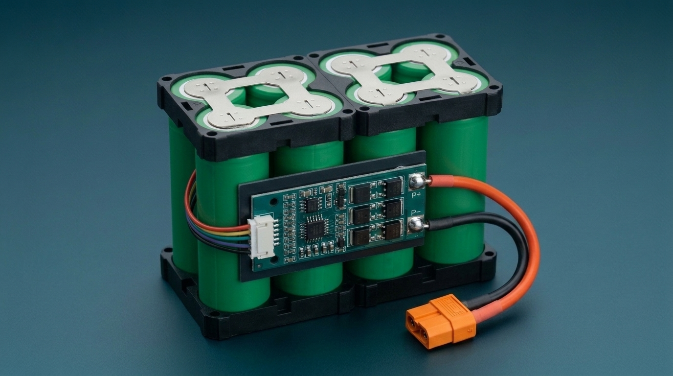 CONCEPT IMAGE